Our services

We help you to take your microfluidic project to the next level

Microfluidics: microfluidic chips manufacturing

Contract Manufacturing


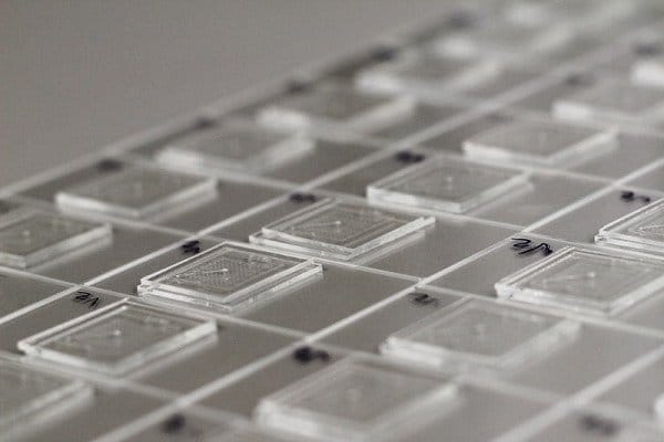
If you need tens of microfluidic devices for experimentation, hundreds for trials or validation, or thousands for product launch, uFluidix can help. We use a Quality Management System (QMS) to enforce product reliability.

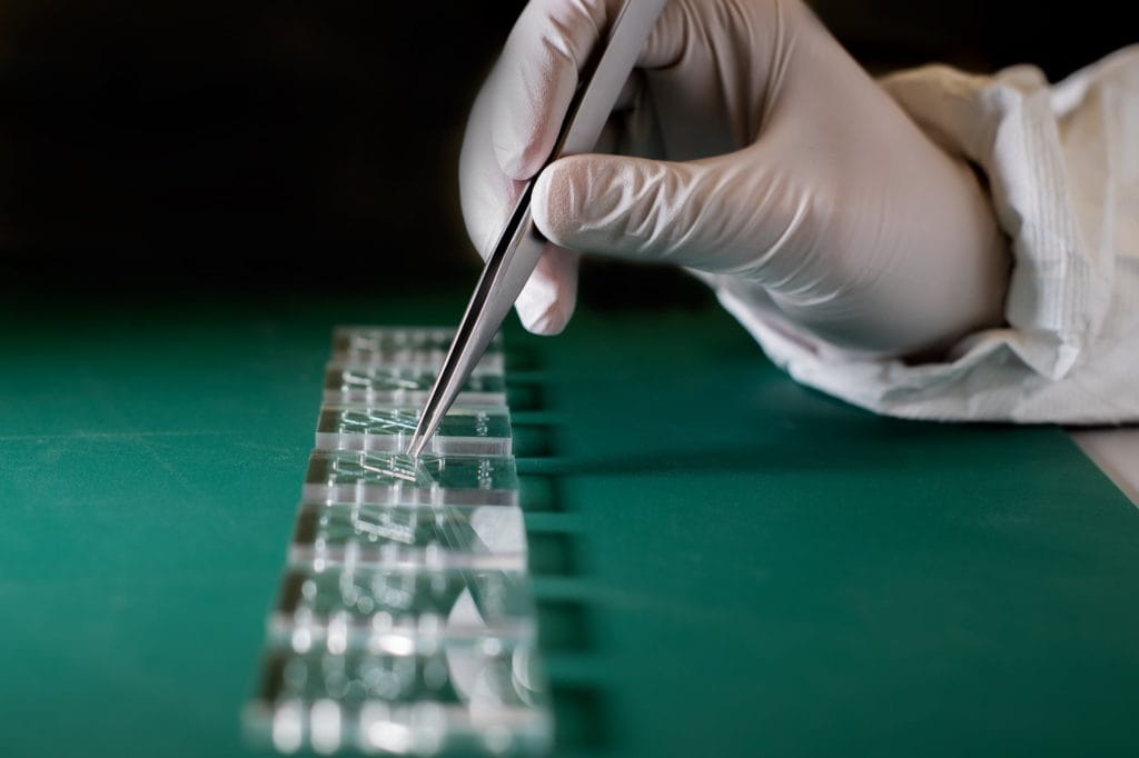
The microfluidic chip manufacturing, handling and packaging are performed in our industrial cleanroom facility. All toolings, molds, and fixtures are fabricated in-house for faster turnaround and protection of the client’s IP.

uFluidix uses proprietary scalable bonding processes for the production of Microfluidic Chips which best fit each device’s channel requirement including contact angle, chemical/solvent or biological contaminants, inhibitory agents, roughness, or optical/fluorescence issues. Microfluidic channels are made from a plastic/glass/silicon/silicone layer covered by additional layers. The sealing strength between the layers is critical to the performance of the Microfluidic device. On the other hand, the conventional multilayer bonding methods used in foundries are not appropriate for large volume production creating a bottleneck to the production process. We help our clients to adopt scalable manufacturing processes suitable to their needs.

Click on the icons below to find more information about microfluidics:

Prototype Fabrication


Very recently, the use of Microfluidics in applications such as Sequencing, Personalized Medicine, Drug Discovery, Gene Therapy, Wearables, and Point of Care Testing is accelerated. We see a rush in industry activities in bringing these microfluidic solutions to the market. Many startups and spin-offs with brilliant Microfluidic intellectual property are appearing fast. Alternatively, there are promising products being pushed by the established Medical Device and Pharmaceutical industry.

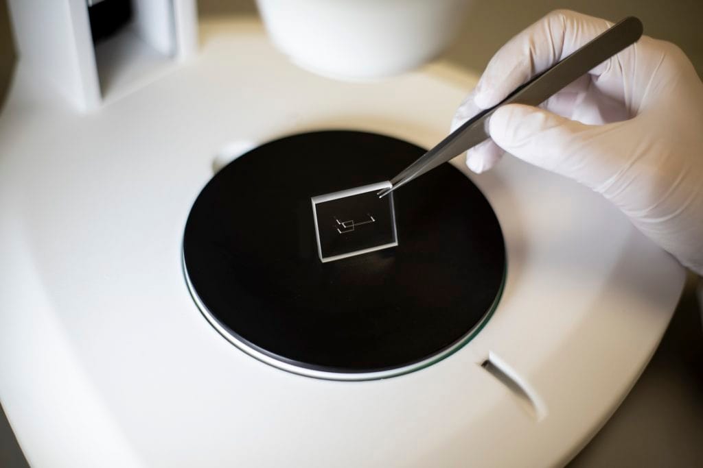
We understand how crucial it is for our clients to quickly and efficiently fabricate their microfluidic design so they can move to the next iteration. Our turnaround for prototyping Microfluidic devices is often faster than your procurement department to purchase our products.

microfluidic chip fabrication
Microfluidics Resources

Design and Development


Several years of experience have rewarded uFluidix with knowledge proven to be critical for Microfluidic product development in a wide range of applications. If you are currently conceptualizing, improving, or validating a Microfluidic application from the list below we invite you to a friendly chat with one of our development specialists. We ensure you would hear something from us that is worth the experience.

How Are Microfluidic Channels Designed for Manufacture?

Manufacturability of a microfluidic device is a matter of make or break when it comes down to new microfluidic product success. uFluidix engineers have helped thousands of projects for manufacture, where they encountered and solved fabrication issues in many of them. We can tell you from the get go if your microfluidics is ready to manufacture, or need some changes or perhaps needs to be scrapped due to manufacturing limitations. Here we described manufacturability for microfluidic channels.

Microfluidic Channels are used for a wide range of applications. The main function of a microchannel in continuous microfluidics is to bring liquid into the microfluidic device. The liquid could be media such as PBS, water, or oil. Or it could be a liquid specimen such as, blood, sweat, saliva, urine, semen, or sewage water. The liquid may carry microparticles such as cells, organoids, hydrogel beads, or magnetic beads, tc… The fluid may contain chemicals or reagents such as drugs, dyes, enzymes, or nutrition. Similarly, the liquid could be a reagent for chemical synthesis such as monomers, or extraction such as organic solvents. In most cases, the microfluidic channel takes the waste or product out of the microfluidic chip as well. For example in organ-on-a-chip microfluidics, the cells are cultured inside a microfluidic chip. After food and possibly drug is fed to them, cells’ waste and the used media are pumped out. Alternatively sometime products need to be collected from the microfluidic device. For instance in droplet microfluidics, the microchannel delivers the droplets and their encapsulation out of the microfluidic chip for more processing. Another example is mixtures produced in micro mixing devices. In addition to fluid delivery, microfluidic channels themselves could be functional. For instance, they may function as a reaction chamber, separation channels, imaging chamber, and many more in microfluidics.

Regardless of the purpose of having the channels in microfluidics, there are certain rules and limitation that govern their design enforced by fabrication processes. It is best to consult an experienced Microfluidics manufacturing company such as uFluidix to assess manufacturability of the microfluidic channels in your design.

Here is a quick list of some microchannel design tips:

  • The ports and channels need to be properly distanced from each other or from the microfluidic chip’s boundary to avoid leakage.
  • To avoid de-molding issues, the microfluidic chip should not be overcrowded with features.
  • To help with cutting and dicing of the microfluidic chips, and to prevent warping, keep the layout as a rectangle.
  • Avoid circular cross section for the microchannels. The best cross section is square.
  • Avoid too wide channel (small aspect ratio) or too narrow channels (large aspect ratio).
  • Keep the depth along the channels constant as much as possible. If there is a need to change the depth do it stepwise. Less steps corresponds to lower fabrication cost.
  • Avoid negative draft angle in microfluidics.
  • Avoid overhung Microfluidic features.
  • Avoid creating unnecessary pressure in microfluidics due to design mistake. We elaborate this popular mistake a bit more here.
Microfluidic Chips

Longer channels in microfluidics create higher pressure linearly. This means if pressure at the inlet of the microfluidic device is 1 Bar for a 10mm channel, it will be more or less about 2 Bars if the channel length is increased to 20mm. Smaller cross section also causes higher pressure in microfluidics. This means inlet pressure created in a 100umx100um cross section channel is much higher than a 200umx200um channel, at the same flow rates and channel length. uFluidix presents an online calculator to estimate the pressure for different fluid viscosity, flow rates, and channel geometries. To reduce such pressures  avoid this popular design mistake: Often the designers of microfluidics make the channels too long unnecessarily. For instance if the area of interest is 10mm there is no need to have a 10 cm microchannel. A total of 25mm channel would do the job.  This would reduce the pressure to about 1/4 in this case. If there are certain parts of the design that must have small width, then a two layer mold could be used. As an example, if a junction must be 10umx10um, the rest of microchannel from inlet to just before the junction, and from after the junction to the outlet could be made as a 100umx100um cross section. This could reduce the pressure at the inlet few hundred times!

Why Prototype Microfluidics Before Large Volume Manufacturing?

A wide spectrum of companies uses uFluidix’s reliable manufacturing services for producing microfluidic component of their products. These clients receive the microfluidic parts from uFluidix and integrate them with their microfluidics-based cartridge or analyzer for selling to their own customers. uFluidix uses strict quality management protocols and the highest standard of precision manufacturing for success of the client’s product. We believe increased sales of our clients translate to our own growth, and therefore we obligate ourselves to deliver the best manufacturing service.

But the path toward large volume production of microfluidics pass through smaller volumes or prototyping stages. Many of our newer or returning clients use our rapid and efficient Microfluidics prototyping services. These custom fabrication projects range from trying novel microfluidics concepts as part of a product development cycle to academic research. Nature of a microfluidics prototyping service is very different from any manufacturing project. Clients usually need the microfluidic prototypes swiftly, sometime in a few days. The quantities for prototyping are small, ranging between 5-1000 microfluidic chips. The designs are often more complicated than a manufactured microfluidics-based product, requiring deep microfabrication knowledge and very niche skills to realize the concept. Equipment, tooling and molds for these custom fabrication projects are entirely different. In addition, the quality inspection of such microfluidic prototypes are performed by personnel instead of machines.

To summarize, prototyping is needed:

  • for functional testing of the Microfluidics
  • to evaluate mechanics of the fluid and features in the micorlfuidc device
  • for visualizing flow stability in the microfluidic channel
  • to examine bubble formation in the microfluidic chip
  • to observe stagnation points
  • for microchannel surface characterization
  • for testing assay performance in microfluidi chip’s micro-environment
  • for studying cell adhesion, propagation, communication, or viability in the micro-environment
  • to learn about possible functionality issues caused by manufacturing limitations such as fidelity or tolerance, or
  • to choose a proper material for the microfluidics. The microfluidic chip material needs to meet critical design requirements such as thermal, optical, mechanical, or chemical compatibility.
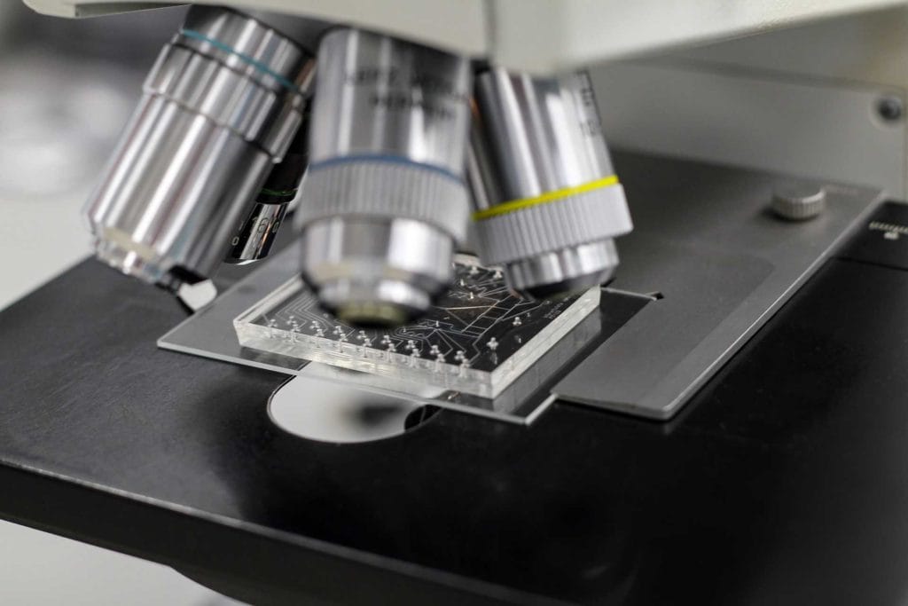
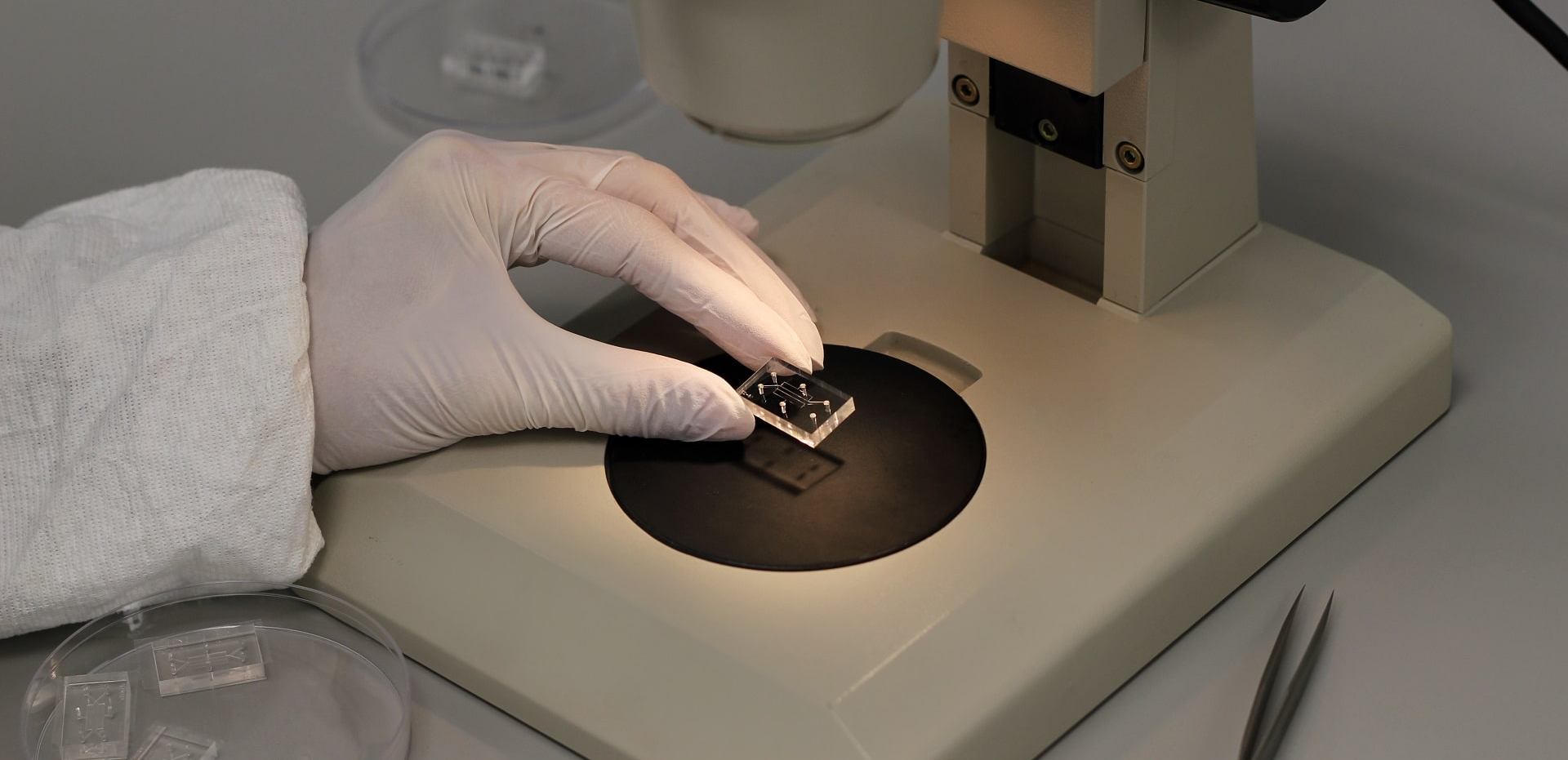
Microfluidic device under the microscope

The most efficient prototyping strategy is to breakdown the concept to sub-component level, test them then add them together one by one toward a final more complicated design. This would save time and money. For example consider a diagnostic Microfluidics based cartridge with micromixers, valves, and reaction chambers. In this example it is a good practice to prototype the microfluidic chambers, mixers, and valves separately. The design parameters of each of these components could be independently optimized using the prototypes.

Final Important Words: “Transfer to manufacture”.

A microfluidics prototype that could perfectly model your design, does not tell you much about its manufacturability. It is very important to outline the final manufacturing process from early stages of the microfluidic product development. Cost to produce a microfluidic chip in large volumes could be reduced few times if designed for manufacture. We have seen many designs that work perfectly in prototype level, but don’t deliver once manufactured. We, as a Microfluidics manufacturer, have seen companies who burned millions of investment dollars, and went out of business in few years due to incorrect or nonexistent design to manufacture strategy.

Materials for Microfluidics

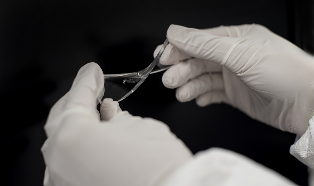
Polydimethylsiloxane aka PDMS is the material of choice to kick off most microfluidics projects. It is also the most suitable material for many applications, as we would discuss here. Most microfluidic projects are first tested in PDMS mainly because of its fast prototyping turnaround. If all the equipment and skills were present in a microfluidics research group, new microfluidic prototypes could be fabricated in few days, sometime in just one day. Also cost of the first iteration is reasonable so microfluidics researchers could try several ideas or design parameters. PDMS, however, might not be the material of choice for large volume (+100,000 /year) type projects. The main reason is that it has a cure time of minimum of one hour. In contrast, an injection molded thermoplastic part, can be realized in few seconds, making the injection molding process more suitable for large scale manufacture of the microfluidics.

So how PDMS could be the material of choice for some applications? There are few reasons: first is the extremely fine resolution of the PDMS microfluidics features. Uncured PDMS is a low-viscosity pre-polymer, making it suitable to have nano-level mold features. This means even sub-micron microfluidics features could be fabricated. If a microfluidic applications must use features smaller than 10um to perform, then PDMS microfluidics is the answer. Such sizes are very difficult to achieve using any other material. Such PDMS microfluidic parts have another interesting geometrical property, called high fidelity. For example if a part has a 10um feature that needs to be very sharp at a junction, then PDMS microfluidics part could provide the sharpness. A 20umx20um square would look pretty much like a square after casing in PDMS, while in thermoplastics a 20umx20um feature would mostly come out as a rounded feature.

PDMS Microfluidics has several other advantages unmatched by other materials. It is an elastomer, meaning the mechanics is tissue-like, which make PDMS very attractive for tissue chips, organ on a chip, human on a chip, organoids manufacture, microenvironment controlled cell culture, etc. It has close to zero autoflourescence meaning for microfluidics applications requiring fluorescence imagining such as cell sorting or staining is very suitable. And finally PDMS Microfluidics parts could be sealed to other PDMS parts or few other materials without needing glue or heat. Thermal or laser bonding is the method of choice to package thermoplastic microfluidics parts, but the method could distort the channel geometry and requires fine process optimization to achieve a reasonable trade-off.

If microfluidics feature resolution, fidelity and high aspect ratio are requirements of your design, then the only material that could be considered as an alternative to PDMS is Silicon. Silicon wafer (similar material as used in solar panels) could be shaped to very fine features and high aspect ratio channels using a genius process called Deep reactive-ion etching (DRIE). Microfluidic chips made by DRIE are diced, drilled and bonded to a seal layer. Bonding silicon chips is challenging, and the silicon material is opaque. But silicon chips provide excellent platforms where electrical or thermal conductivity is needed.

Glass microfluidics chips are also interesting. The glass parts are often made by a process called wet etching. The process is suitable for larger size channels. Creating access ports requires drilling that makes glass unfit for volume manufacturing. Also glass microfluidics parts need high pressure and temperature for being sealed. The main advantage of glass over all other materials for microfluidic manufacturing is its chemical compatibility. Materials such as PDMS or thermoplastics are not compatible with most concentrated organic solvents or acid/base liquids. In addition glass chips could take temperatures above 200C. Most thermoplastics stop at 120C, while PDMS Microfluidics chips are good below 200C.

Thermoplastics such as Poly(methyl methacrylate) (PMMA), Polycarbonate, Polystyrene, or  Cyclic olefin copolymer (COC) or polymer (COP) are excellent candidates for large volume production using injection molding. Commercial names for PMMA are acrylic glass or plexiglass. Polycarbonate is called as Lexan or Markrolon. And polystyrene is the material for most Petri dishes. The main drawback of thermoplastics microfluidics is the feature size and fidelity. Although there are reports of injection molding or microinjection molding to be able to produce high aspect ratio or micron size features, the microfluidic designer must be aware that such achievements are gained under specific circumstances which most likely is not applicable to volume manufacturing of their microfluidic chips. An alternative process to achieve reasonable feature size in thermoplastics is hot embossing. Although this method produces fine features, but one need to consider that finer feature size or high feature fidelity costs time. To fabrication process to reach 95% fidelity at 10um feature level could take as long as 3 hours for embossing one mold. The molds also are costlier than other manufacturing processes.

What Affects Pricing of Custom Microfluidics Fabrication?

The direct cost of producing custom made microfluidic devices has two parts to it.

1) Tooling

2) Per chip cost.

There are many factors affecting the microfluidics chip price. Here are top contributors:

  • quantity of the microfluidic devices in the purchase order
  • complexity of the fabrication protocol
  • quality control requirements of the mcirofluidic chips
  • geometrical requirements such as minimum feature size or minimum/maximum aspect ratio, or feature density/population
  • microfluidic chip material system
  • microchannel surface fictionalization needs. These factors need to be discussed in prototyping or manufacturing schemes separately.

Final word here is that in Microfluidics fabrication, smaller generally means more expensive. Although there is some raw material saving when miniaturizing a design, the follow-up costs related to production and QC of the microfluidics exceeded the material saving by orders of magnitude. When developing the microfluidics based product, the sustainable Cost of Goods Sold (COGS) or direct cost must be displayed on the designers’ desk and kept on mind before moving to prototype stage.

Microfluidics: PDMS Material

Microfluidics Prototyping Pricing


Here we present top parameters affecting price/chip of  microfluidics prototypes from the most important to the least. For microfluidics prototyping the most contributing factor affecting the price is quantity in one order. Assuming the tooling cost to fabricate 1 or 100 prototypes of a microfluidic chip is the same, the price/chip could easily see a 10-fold difference based on the quantity. Obviously larger quantity corresponds lower /chip  cost. This is because we batch work, often batch several different projects, to reduce the cost for the client.

Second factor is the complexity of fabrication.

Third factor is the microfluidics material system, for example a glass-thermoplastic chip is more expensive than a PDMS-glass microfluidics chip.

Fourth important factor is the feature size. Feature size and geometry mainly affect the tooling type and its associated cost in custom prototyping of microfluidics, not the /chip cost.  It is more expensive to manufacture metal molds than DRIE mold than photoresist mold than micromachined mold than 3D printed molds!

Fifth factor affecting the price is surface functionalization of microchannels, and finally the sixth factor is the quality inspection of the microfluidics.

Microfluidics Manufacturing Pricing


The pricing formula is different for manufacturing of thousands per year of microfluidics chips compared to prototyping a handful of microfluidic devices. Here again we try to present the big picture. Each project has its own requirement and could be different.  Manufacturing of thousands to millions of microfluidic chips requires automation. Automation equals capital costs. So any factor that makes automation costlier directly increases the microfluidic chip price. Full automation’s capital costs could only be justified when the volume of production for the chips exceeds a million or so per year.  So again quantity of the purchased chips could be the first contributing factor here.

Complexity as mentioned in prototyping also plays a major role here. Multilayer chips requiring micron level alignment and bonding don’t fit well with conventional automated processes such as laminating.

Quality control of a large volume of Microfluidics products would be like an obstacle. Unlike Microfluidics prototyping where QC was not a cost driver, The QC in manufacturing could be even costlier than manufacturing the chips themselves. Automated imaging and analysis with the help of Artificial Intelligence is the way to go, but a highly populated chip with micron level features would be challenging to zoom/unzoom and record and track the images.

The next factor affecting price of microfluidics manufacturing would be channel functionalization. Functionalization methods such as fixing markers, or silanization require sequential steps, meaning each microfluidic chip needs to be treated one by one to complete the process. This is not a scalable process in which a batch of 1000 chips could be treated all together. So functionalization in manufacturing is an important cost to consider.