The undesired appearance of bubbles is a common occurrence when working with microfluidics. Anyone who works in the field has almost certainly suffered from bubbles appearing at the least convenient moment. However, removing bubbles is not only a matter of convenience and to generate data for a scientific publication. Commercial microfluidic applications require robust solutions involving avoiding bubbles without compromising on the functionality of the device.
Why do bubbles form in a microfluidic set-up?
Any liquid presents a certain amount of dissolved gases, which depends on the solubility of each gas. But why does the dissolved gas suddenly form a bubble? Changes in temperature and pressure are often the leading cause. Pressure can change within the microfluidic set-up due to the way in which liquids are injected or aspirated. While liquids under high pressure can hold high amounts of dissolved gas, liquids under lower pressures present lesser gas solubility and are thus bubble prone. Temperature variations are usually less common in the microfluidic set-up, unless explicitly present because of the experimental design. A common situation where the researcher unintentionally alters the system temperature is when a liquid reagent is used right after getting it from the fridge. Liquids at low temperatures have higher gas solubility than at room temperature, so if the liquid is not equilibrated before, it will potentially increase the risk of bubbles.
These environmental changes are however not enough for a bubble to form: a nucleation point is required. Although it is theoretically possible that a number of molecules spontaneously meet and form a bubble of a radius larger than the critical radius needed to grow, this is rather unlikely. There is a need for a ‘catalysts’ (Harvey nuclei), such as small irregularities on the surface, where nanoliters of air are trapped. The gas can only be trapped if the contact angle of the liquid has low wettability and cannot fill the irregularity. This gas will remain stable while conditions no dot change. However, if the pressure of the surrounding liquid is altered, it will either dissolve the gas or create a flux of gas inside it, producing a net growth of the bubble. This bubble can then block the microfluidic channel or migrate towards other regions of the chip, potentially damaging the experiment. The nucleation point will still remain at the same spot, generating new bubbles1. So what would be the possibilities to avoid them altogether?
How can bubbles be avoided?
Understanding how a microfluidic system works is the first step to find ways to avoid bubbles. From deciding which liquid one needs to the design of the chip, all steps have to be performed considering that bubbles can appear. This section will briefly go through the most common ways to avoid bubbles. For further details about these conditions, one can read the review from Pereiroet al1.
Considering the physics of bubble formation, the following conditions are the best to avoid bubbles:
- Pressure. A reduced pressure gradient is preferable to a high one.
- Temperature. It is better to keep the whole microfluidic set-up at a constant temperature.
- Time. The shorter the experimental time, the less probabilities of bubbles growing to the point of altering an experiment.
These conditions are of course quite limiting, so other strategies are required. For instance, when designing a chip, there are some structures that it is better to avoid -or at least reduce in use-, since they are prone to form bubbles. The most common of these structures are:
- Dead ends, microwells, and sharp corners. Wetting in these structures is difficult and air can be trapped (Fig. 1a and 1b). These structures can be functionalized to increase their wettability.
- Wide low chambers. The use of these chambers is very common in microfluidics to perform reactions or to grow cells (Fig. 1c). However, the liquid front tends to have different speeds on both sides of the chamber and thus, a bubble can potentially form. The use of phase-guides might avoid the liquid front from advancing too fast in one direction than in the other. Pillars are another structure that equalizes the speed of the liquid front.
- Contact regions between two parts of a device. The surface where binding between two parts happens usually present irregularities, being a great place for bubble nucleation (Fig. 1d). Therefore, it is recommendable to use a cladding material to bind these structures.
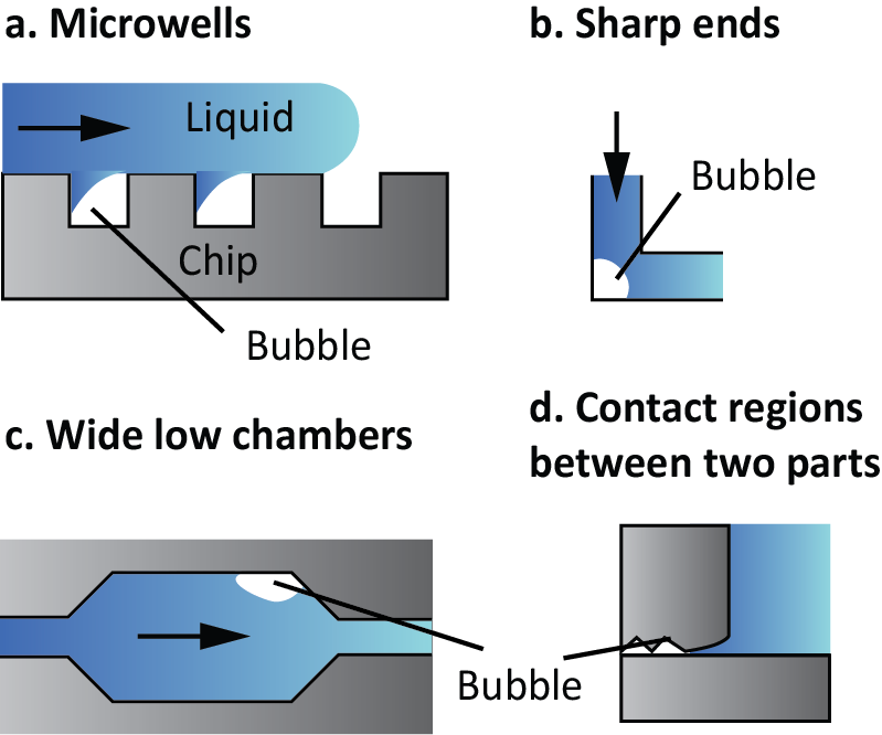
Figure 1. Examples of structures that tend to generate bubbles.
The structure is not the only thing to consider during chip design, as the material can also influence bubble formation. Hydrophobic materials, such as PDMS, tend to be sources of Harvey nuclei. In this case, treatment with oxygen plasma increases the hydrophilicity of the chip for a certain period of time. Another possibility is the functionalization of the material with hydrophilic groups.
Although the chip is the part of the microfluidic system that gets the most attention, the rest of peripherals and connections are equally important. These are some steps that might reduce the probability of bubbles product of this part:
- Check the sealing of all interfaces. Air is often introduced without the user noticing, and many issues can be avoided simply by improving the sealing between connectors. Glues and epoxy resins can be very helpful to improve the sealing2.
- Reduce the presence of dead areas. Similar to the previous point, air can be potentially introduced in inefficient world-chip connections. Chips must be designed to avoid dead areas in the connector regions.
- Reduce the number of connectors to the minimum. Each connection provides a potential nucleation point for bubbles.
- Place the necessary connectors closer to the reservoir. The further we are from reservoirs o reagents, the more likely it is that the conditions change, and nucleation points are generated.
What to do if bubbles happen anyways?
The aforementioned conditions are an idealized case scenario and it is likely that some of them will not be applicable for a particular system. In this case, there are some contingency measures to be taken after bubbles have appeared:
- Flush ethanol or ethanol: water mix before the experiment. If it is known that the chip is bubble-prone due to the presence of some unfavourable structures and the contact angle of the liquid will not permit a complete wetting, using a liquid with a lower wetting angle might help to remove stuck bubbles.
- Flushing of liquid at high flow rates. This helps to detach the bubbles and remove them from the system. It will not work if there is an irregularity constantly producing bubbles.
- Dissolve the bubble into the material. If the material used is permeable to gas, such as PDMS, one can increase the pressure inside the chip to force the bubble to dissolve into the material.
- Degassing of reagents. This step is especially helpful when other solutions have failed and the system does not allow for bubble traps.
One of the more straightforward strategies to remove formed bubbles is the addition of a physical bubble trap. Some bubble traps can be directly incorporated into the chip upon its design, while others can be attached as an external module to an already existing chip. The strategies for a bubble trap can be summarized in:
- Addition of physical elements that stop bubbles. An example of this strategy can be found in the bubble trap proposed by Sung et al3, where the authors incorporated sieve-like structures in a chamber to stop bubble progression.
- Use of a permeable material. Lochovsky et at4 developed a chamber that captures bubbles and then, through the application of vacuum, the bubbles are removed from the chamber. Bubble traps from commercial suppliers usually follow this strategy as part of an external module (see bubble traps from Fluigent or Elveflow as an example).
- Use of the hydrophobicity of material to capture bubbles. Due to the low surface energy, bubbles tend to stay on hydrophobic materials. This property was used by Cheng et al5 to develop a bubble trap with an “energy sink”, where bubbles would get stuck instead of migrating to more critical areas.
It is important to note that there is no single way of avoiding or removing bubbles as there is no single cause for bubble formation. Each user needs to analyze their system to find the best way to produce a robust device. Nevertheless, a good understanding of the physics behind bubble formation is a great way to combat them. Then, hopefully, bubbles will be a thing from the past.
Featured image credit: Lorenzo Petrini
References
1. I. Pereiro, A. Fomitcheva Khartchenko, L. Petrini, I. Pereiro, and G. Kaigala, “Lab on a Chip Nip the bubble in the bud : a guide to avoid gas nucleation in microfluidics,” Lab Chip, 2019. See paper summary in: https://www.youtube.com/watch?v=eBu0lA6jFq0&t=
2. Y. Temiz, R. D. Lovchik, G. V. Kaigala, and E. Delamarche, “Lab-on-a-chip devices: How to close and plug the lab?,” Microelectron. Eng., vol. 132, pp. 156–175, 2015.
Last accessed: 03/01/2019.
3. J. H. Sung and M. L. Shuler, “Prevention of air bubble formation in a microfluidic perfusion cell culture system using a microscale bubble trap,” Biomed. Microdevices, vol. 11, no. 4, pp. 731–738, 2009.
4. C. Lochovsky, S. Yasotharan, and A. Günther, “Bubbles no more: In-plane trapping and removal of bubbles in microfluidic devices,” Lab Chip, vol. 12, no. 3, pp. 595–601, 2012.
5. H.-B. Cheng and Y.-W. Lu, “Applications of textured surfaces on bubble trapping and degassing for microfluidic devices,” Microfluid. Nanofluidics, vol. 17, no. 5, pp. 855–862, Nov. 2014.
Enjoyed this article? Don’t forget to share.

Anna Fomitcheva Khartchenko
Anna Fomitcheva Khartchenko is a doctoral student at ETH Zurich performing her research at IBM Research-Zurich. Her research interests are in leveraging microfluidics with protein analysis and quantification as well as cancer diagnosis.

