04 Nov The Dawn of Microfluidic Transistors: Paving the Way for Advanced Lab-on-a-Chip Devices
In a groundbreaking study, researchers have unveiled a microfluidic transistor that mimics the functionality of its electronic counterpart, marking a significant leap in the field of microfluidics. This innovation could revolutionize the way we manipulate fluids at the microscale, with far-reaching implications for molecular biology, synthetic chemistry, diagnostics, and tissue engineering.
“Previous works on creating a microfluidic analogue to the electronic transistor did not replicate the transistor’s saturation behaviour, and could not achieve proportional amplification, which is fundamental to modern circuit design. Here we exploit the fluidic phenomenon of flow limitation to develop a microfluidic element capable of proportional amplification with flow–pressure characteristics completely analogous to the current–voltage characteristics of the electronic transistor.“, the authors explained.
The microfluidic transistor exploits the fluidic phenomenon of flow limitation to achieve proportional amplification of fluidic signals. This capability is fundamental to modern circuit design and has been a critical need in the field of microfluidics. The device’s flow-pressure characteristics are analogous to the current-voltage characteristics of an electronic transistor, marking a significant advancement in the field.

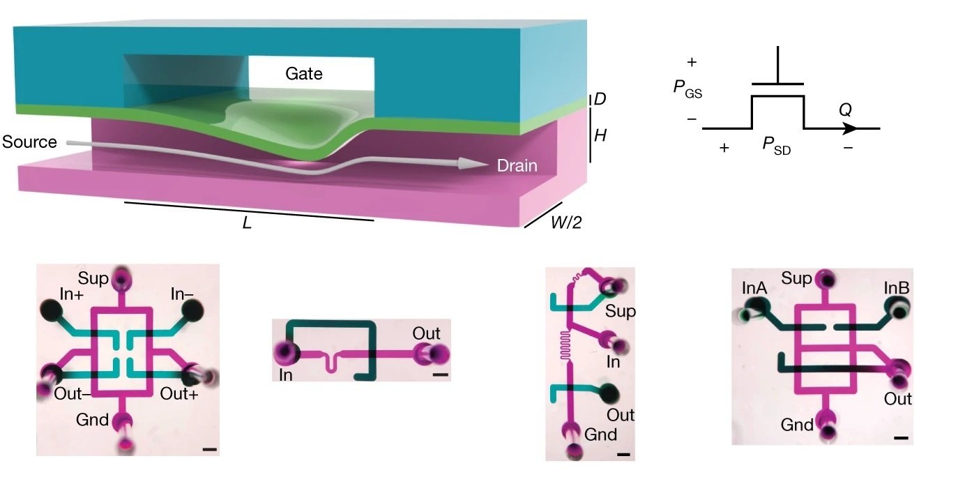
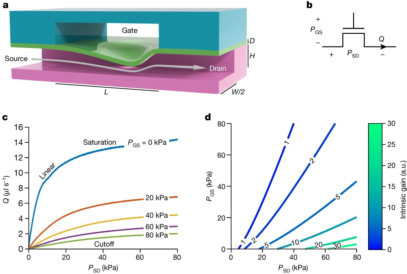
“a, Longitudinal section of the microfluidic transistor, fabricated from two layers of thick elastomer with channels (magenta, teal) and a thin elastomer membrane (green). Pressure applied between the gate and the source deflects the membrane, restricting flow (arrow) from the source to the drain in a nonlinear fashion known as flow limitation. b, Schematic symbol for the microfluidic transistor. The pressure difference between the gate and the source is PGS, and the pressure difference between the source and the drain is PSD. Volumetric flow through the drain is Q. c, Experimentally measured characteristic curves of the microfluidic transistor, demonstrating all three operation regimes seen in electronic transistors (linear, cutoff and saturation). d, Contour plot of the intrinsic gain of the microfluidic transistor as a function of PGS and PSD, depicting a large region with intrinsic gain greater than one. a.u., arbitrary units.” Reproduced from Gopinathan, K.A., Mishra, A., Mutlu, B.R. et al. A microfluidic transistor for automatic control of liquids. Nature 622, 735–741 (2023). under Creative Commons Attribution 4.0 International License.
Microfabricated from layers of thick PDMS using standard soft-lithography techniques, the microfluidic transistor is designed with two crossed channels separated by a thin, deformable elastomeric membrane. At the heart of the microfluidic transistor’s operation is the phenomenon of flow limitation. By applying a pressure difference across the source and drain terminals, the membrane deforms, leading to a controlled restriction of flow. This behavior is modulated further by adjusting the pressure between the gate and source terminals, akin to tuning an electronic transistor. The device’s ability to replicate the linear, cutoff, and saturation regimes of electronic transistors is a remarkable feat, showcasing its potential to serve as a fundamental building block in fluidic circuitry.
The validation of the microfluidic transistor’s performance is as robust as its design. Characterization involved sweeping the pressure difference across the source and drain while holding the gate-source pressure constant, revealing the characteristic curves that define the transistor’s operation. Some of the validations for the microfluidic transistor involved:
1- Characteristic Curves: The device exhibits characteristic curves that demonstrate linear, cutoff, and saturation regimes, akin to an electronic transistor. These curves are crucial for understanding how the device will behave under different operating conditions.
2- Intrinsic Gain: A significant finding is the large operating region where the intrinsic gain of the microfluidic transistor is much greater than one, indicating its capability for proportional signal amplification. This intrinsic gain is a critical parameter that quantifies the maximum proportional amplification achievable.
3- Shapiro Number: The research confirms that when the Shapiro number exceeds one, the flow-pressure characteristic of the transistor enters flow limitation. This number is a dimensionless measure that indicates the onset of flow limitation in the system.
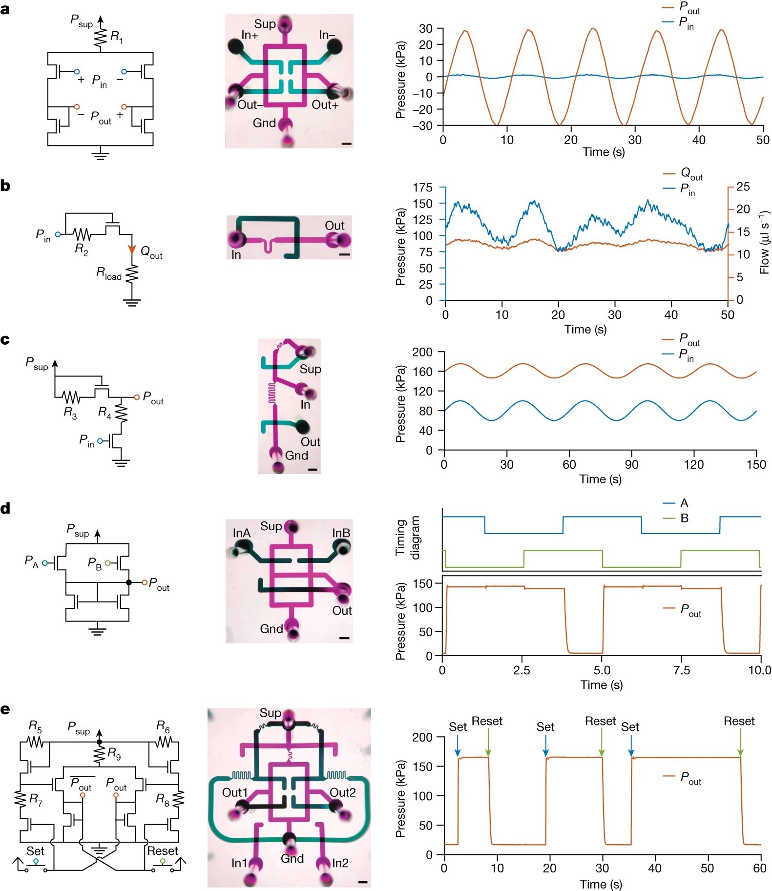
4- Flow Regulator Performance: The transistor was tested as a flow regulator, where an input pressure varying from 75 to 150 kPa was regulated to supply a consistent target flow of 1.2-1.5 µl/s to a load. This test demonstrates the transistor’s ability to maintain a stable flow rate despite variations in input pressure.
5- Circuit Implementation: The microfluidic transistor was used to replicate key electronic circuits in the fluidic domain. For instance, a fluidic differential amplifier was demonstrated, amplifying an input differential pressure signal with a gain of 2.2 to generate the output differential signal.
Further tests included the translation of classic electronic circuits into the fluidic domain. The team successfully demonstrated on-chip fluidic signal processing with a suite of fundamental circuit topologies: amplifiers, regulators, level shifters, and logic gates, all without reliance on external control systems. The culmination of these tests was the autonomous particle dispenser circuit, which integrated signal processing with physical sample manipulation, autonomously sorting single particles in a deterministic manner.

“For each circuit, the schematic diagram (left), a photo of the microfluidic implementation with ports labelled (middle; false colour; scale bars, 1 mm) and a representative demonstration of circuit function (right) are provided. Microfluidic port labels are defined and detailed in the Methods and Extended Data Figs. 7 and 8. Power supply and ground ports are labelled ‘Sup’ and ‘Gnd’, respectively. a, A fluidic differential amplifier. The input differential pressure signal (blue, applied at ‘In+’ and ‘In–’) is amplified with a gain of 22 to generate the output differential signal (orange, measured at ‘Out+’ and ‘Out–’). b, A flow regulator. The input pressure (blue, applied at ‘In’) varying from 75 to 150 kPa is regulated to supply a target flow (orange, measured at ‘Out’) of 12 ± 1.5 μl s−1 to a load. c, A level shifter. The baseline of a varying input pressure signal (blue, applied at ‘In’) is shifted up by 80 kPa to produce an output pressure signal with the same morphology (orange, measured at ‘Out’). d, A NAND gate. The output signal (orange, measured at ‘Out’) is low only if both input signals (blue and green, applied at ‘InA’ and ‘InB’) are high. e, An SR latch. The persistent state of the latch (orange, measured at ‘Out2’, complement state measured at ‘Out1’) can be set to high or low pressure based on transient pulses applied to ‘set’ (blue) or ‘reset’ (green) the input ports ‘In1’ or ‘In2’ high or low.” Reproduced from Gopinathan, K.A., Mishra, A., Mutlu, B.R. et al. A microfluidic transistor for automatic control of liquids. Nature 622, 735–741 (2023). under Creative Commons Attribution 4.0 International License.
“Overall, the combination of EV metabolic labeling and efficient microfluidic enrichment improve our ability to accurately analyze EV secretion over time, which should enable the study of EV secretion mechanisms as well as the in-depth exploration of EV biological function and clinical value. Besides adding a temporal dimension to our understanding of EV dynamics in immunotherapy, in principle Melac-Chip can also be applied to study EV dynamics that is stimulated by a broad range of cues, such as microbial infection, environmental (temperature, light, and gravity) variation, and diet change.“, the authors concluded.
The microfluidic transistor opens up possibilities for more sophisticated on-chip automation, enabling researchers to design complex fluidic circuits that can operate independently of bulky peripheral equipment. This autonomy is crucial for the development of truly portable and field-deployable lab-on-a-chip devices.
For more insights into the world of microfluidics and its burgeoning applications in biomedical research, stay tuned to our blog and explore the limitless possibilities that this technology unfolds.
Figures are reproduced from Gopinathan, K.A., Mishra, A., Mutlu, B.R. et al. A microfluidic transistor for automatic control of liquids. Nature 622, 735–741 (2023). https://doi.org/10.1038/s41586-023-06517-3 under a Creative Commons Attribution 4.0 International License)
Read the original article: A microfluidic transistor for automatic control of liquids


